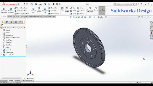
Posts

Showing posts from September, 2020

Gear

Image
 GEAR Gear is disc with several teeth on their circumference.   Varying torque/Speed, direction of movement is the function of gear and based on design and construction, its applications differs. DESIGN OF GEAR Assumptions Number of Teeth (N)     = 25 Module (Standard)(m)   = 10 Pressure angle                  = 20 ° CALCULATIONS Addendum                                         = 10 Dedendum                                          = 1.125 × 10 = 11.25 mm Pitch Circle Diameter (d)                = m × N = 10 × 25 = 250 mm Outer diameter (OD)                      = PCD + (2 × addendum) = 250 + (2 ×10) = 270 mm Root or Inside diameter (Id)         = PCD - (2 × dedendum) =250 – (2×11.25)= 227.5 mm Circular pitch                                      = ( Ï€ × PCD)/N = (3.14×250)/25 = 31.4 Tooth thickness                                 = Circular pitch/2 = 15.7 mm Youtube link :  https://youtu.be/7QFFtkaTSxM Follow me on instagram: https://www.instagram.com/d

Crankshaft mechanism

Image
Crankshaft mechanism assembly  Tutorial video posted!!!! Crankshaft Mechanism is used in I.C Engines, where the piston reciprocates within the cylinder block, connected to the crankshaft creates a rotating motion. This is an example of slider crank mechanism. Youtube link :  https://youtu.be/o0iBaydzIfA Follow me on instagram:  https://www.instagram.com/designsolidworks01/

Piston assembly

Image
 Piston assembly tutorial video posted!!! Piston assembly  Piston assembly consists of piston rings which surrounds the piston grooves, gudgeon pin which holds the piston and Connecting Rod together.   Youtube link :  https://youtu.be/W_yz1Ss75DE Follow me on instagram: https://www.instagram.com/designsolidworks01/  

Gudgeon pin & Piston Rings

Image
Gudgeon pin and piston rings Modelling Tutorial video posted!!!! Gudgeon Pin A circular rod shaped structure which hols piston and connecting rod together. Material: Steel alloy Dimensions Piston Rings Piston rings are of few types and respective functions such as sealing combustion chamber, heat transfer from hot piston to cylinder. Material : cast iron Dimensions Youtube link :  https://youtu.be/oqWOVu97PRw Follow me on instagram:  https://www.instagram.com/designsolidworks01/

Crankshaft

Image
  Crankshaft Modelling Tutorial video posted!!!! Crankshaft A circular shaft holds a particular shape such that it converts the reciprocating motion of piston to a rotational motion. Dimensions Material: Forged steel & malleable iron Youtube link : https://youtu.be/SbCW2HtU5-c Follow me on Instagram: https://instagram.com/designsolidworks01?igshid=20asl2i3t66w

Connecting Rod

Image
Connecting Rod Modelling   Tutorial video posted!!!! Connecting Rod A mechanical part which connects the piston with crankshaft. Material: Steel, Titanium ,Cast iron   Youtube link : Part 1:  https://youtu.be/2M4XnGuLkN0 Part 2 :  https://youtu.be/ijAwlw8Yp-U   Part 3 :  https://youtu.be/NTY0ZBDENm4 Part 4 :  https://youtu.be/2_HtVUU5gjk Bolt :  https://www.youtube.com/watch?v=SvqCHF8K560 Nut:  https://www.youtube.com/watch?v=j05V_zpakMI&t=65s Follow me on Instagram: https://instagram.com/designsolidworks01?igshid=20asl2i3t66w

NUT

Image
Nut  Modelling           Tutorial video posted!!!! Nut is a part of bolt fastened to hold  two parts together at a point. Material : High Silicon Bronze,  Low Silicon Bronze Dimensions Hole Diameter      : 8 mm  Pitch                          : 1 mm  Revolutions             : 25  Note  : The Pitch and revolutions should be same as dimension used for Bolt.      Youtube link :  https://youtu.be/j05V_zpakMI Follow me on Instagram: https://www.instagram.com/designsolidworks01/

BOLT

Image
Bolt modelling tutorial posted !!! check the below link  youtube link :  https://youtu.be/SvqCHF8K560 Follow me on Instagram: https://instagram.com/designsolidworks01?igshid=20asl2i3t66w

PISTON

Image
Modelling Piston tutorial video posted check the below for the link Piston is a moving component placed between cylinder and connecting rod and is used in reciprocating pumps, engines and gas compressors. Function:   Transfer force from cylinder to crankshaft via connecting rod. Material : Cast Iron & Aluminium Alloy. Dimensions Diameter of piston                                : 90 mm Diameter of pin                                      : 22 mm Ring thickness                                         : 2 mm Distance between the rings                   : 3 mm Thickness of the Groove                       : 20 mm Youtube link :  https://www.youtube.com/watch?v=w3yGg0jUeMc   Follow me on Instagram:  https://instagram.com/designsolidworks01?igshid=20asl2i3t66w

FLYWHEEL

Image
Flywheel tutorial video posted on Youtube Link :  https://www.youtube.com/watch?v=PWegERn_5QY Follw me on instagram :  designsolidworks01 Fly wheel is a mechanical component accelerated by rotor which stores energy as kinetic energy to maintain the rotational energy of a system. Dimensions are taken approximately   Diameter of the rotor                     : 60 mm Diameter of the flywheel             : 260 mm Diameter of the hub                       : 70 mm Thickness of the hub                      : 5 mm Thickness of the flywheel            : 10 mm Number of teeth                             : 100

Turbine Blade

Image
 First video posted on Youtube!!!  Part : Turbine Blade Turbine Blade, a mechanical component used in fluid compressors to move and impart energy to rotor whenever a fluid passes through their blades. Dimensions : Diameter of the Drum : 40 mm Length of the Blades : 80 mm Thickness of the Drum (Width of the rotor assembly) : 50 mm Link : https://www.youtube.com/watch?v=7piB3G5Q7sY Follow me on instagram :  https://www.instagram.com/designsolidworks01/

Introduction to Solidworks

Image
A warm welcome to bloggers who interested in designing and students who are pursuing design related studies this blog is for you to make use of design learning. Solidworks, A vital designing software used for solid modelling by designers. In engineering, I had to go through Solid modelling for laboratory sessions as well as for project work. In this Blog I am gonna post a number of repeated components designed in engineering courses and mechanical parts used in industries which can be made faster than a time consuming design technique. I am using Solid works Service pack 2018 and you can download newer version from below link Download link:  https://getintopc.com/softwares/3d-cad/solidworks-premium-2019-free-download-full-9513641/ Older versions :  https://getintopc.com/ A Turbine Blade modelled in solidworks